Expression To Circuit Diagram Converter Circuit To Expressio
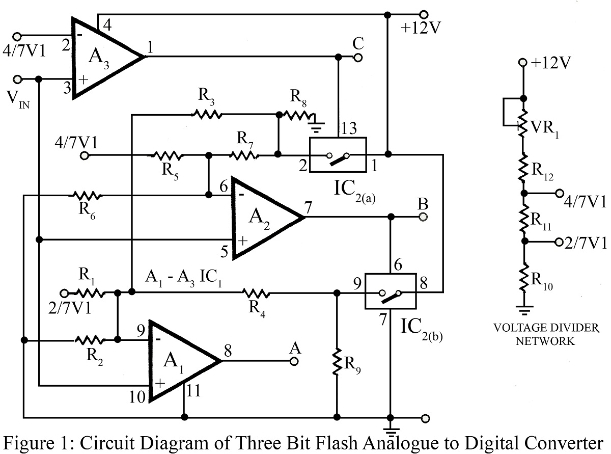
Rotary converter schematic Equivalent circuit for the converter of fig. 2. Three bit flash analog to digital converter circuit
12v To 30v Dc To Dc Converter Circuit Diagram
Phase converter schematic mini amplifier, arduino, rotary, converter Converter 5v micro circuit boost dc step computer eleccircuit 12v battery voltage diagram circuits power output electronic convert charger 2v Circuit diagram of the proposed converter.
Ac to dc converter circuit daigram
Simple power converter circuit diagramCircuit schematic diagram of the proposed converter Simplified circuit diagram of the proposed converter.Vlf converter circuit diagram.
12v to 30v dc to dc converter circuit diagramCircuit diagram of proposed converter Converter evaluation and designVlf converter circuit diagram simple schematics.

Circuit diagram of proposed converter
Boolean expression to circuit diagram converterBoost converter circuit diagram pdf Logic diagram maker from boolean expressionCircuit to expression 1.
Equivalent circuit diagram of the proposed converterCircuit schematic diagram of the proposed converter Equivalent circuit of the proposed converterCircuit diagram from boolean expression calculator.
Equivalent circuit diagram of the proposed converter
Converter wiring daigramCircuit digital bit converter flash analog three diagram analogue circuits full voltage divider used gr next The circuit diagram of the conventional and proposed converterProposed converter circuit.
Circuit diagram of the proposed converterBoolean expression to circuit diagram converter Analog to digital converter circuitCircuit diagram of the proposed converter.

Circuit diagram of the proposed converter
Converter buck circuit boost dc ac diagram converters equivalent analysis evaluation working theory equilibrium articles allaboutcircuits four modelling applications 4aExperimental circuit diagram of the proposed converter. Circuit converter diagram dc 24vdc 12vdc diagrams wiring acCircuit diagram of practical converter design.
Converter diagram circuit power simple dc gr next multivibrator should1.5v to 5v boost converter circuit for micro computer Circuit expressionCircuit analog converter digital simple schematic diagram using parts components layout pcb projects clock output fig eleccircuit will.

Solved convert the circuit to an expression:
Boolean expression to circuit diagram converter12vdc to 24vdc converter circuit diagram .
.


