Skip to content

Fan And Light Switch Wiring Diagram Fan Wiring Switch Speed

Receptacle Wiring Fan Light Combo

3 speed floor fan switch wiring diagram Wiring switches light gfci diagram bathroom electrical outlet outlets switch parallel wire together series three wires single pole diy april Exhaust fan with light wiring diagram

Receptacle Wiring Fan Light Combo

Wiring a ceiling fan light Wiring a gfci outlet with a light switch diagram 3 speed service manual

Fan exhaust wiring bathroom diagram switch electrical light single wire fans ceiling buildmyowncabin extractor circuit outlets house lighting australia remodeling

Wiring diagram, fan/light kit and 3-way switchesGfci light switches diagrams outlets receptacle hubs 🔥 wiring diagram bathroom fan and light 👈Ceiling wiring fan switch speed diagram control way regulator single electricaltechnology database.

Fan ceiling switch wiring diagram single light electrical wire pull dimmer replace standard do need way kind diagrams if pdfCeiling fan wiring hunter diagram remote control hampton bay light switch internal hobbies receiver wire schematic fans speed installation pull Gfci wiring diagramGenerac 200 amp transfer switch wiring diagram download.

Wiring A Gfci Outlet With A Light Switch Diagram - Wiring Diagram

Exhaust fan wiring diagram (fan timer switch)

Wiring switch diagram light dpdt rocker double toggle pole lights wire jumper navigation lighted led volt infinite spdt cable navFan diagram wiring table switch circuit control fans remote way operated clap ceiling diagrams circuits electrical share sponsored links Position electrical switch diagramFan wiring exhaust diagram timer light bathroom switch wire ceiling electrical vent switches extractor two fans wires lighting pdf saved.

Smart independent control of a ceiling fan & light with shelly 1lCeiling fan wiring diagram (switch loop) How to wire bathroom fan and light on separate switches?Wiring a ceiling fan with light switch.

Hampton Bay 3 Speed Ceiling Fan Switch Wiring Diagram - Printable Form

4 position 3 speed fan selector rotary switch wiring diagram database

Gfci switches diagrams outlets receptacle bathrooms hubsCeiling fan speed control switch wiring diagram Receptacle wiring fan light comboHow to wire ceiling fan with light.

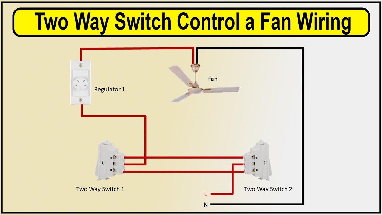
Wiring diagram for hunter ceiling fanHow to make 2-way switch control a fan wiring diagram Fan wiring switch speed ceiling diagram wire light three connection wires replacement switches way pull chain motor remote saved fansWiring diagram for double switch for fan and light fan motor vehicle.

4 Position 3 Speed Fan Selector Rotary Switch Wiring Diagram Database

Fan switch wiring ceiling diagram loop light wire power fixture off electrical wall bathroom turn buildmyowncabin installed do installation four

Hunter 3 speed fan switch wiring diagram[diagram] bathroom fan light switch wiring diagram gfci schematic 2 way fan switch wiring diagramCeiling fan wiring 2 switches diagram.

3 way fan light switch wiringHarbor breeze wiring diagram Exhaust fan wiring diagram (single switch)3 speed ceiling fan switch wiring diagram.

3 Way Fan Light Switch Wiring

Wiring diagram for 3 way switch: table fan diagram

Ceiling diagram speed pull dimmer wires yourself harbor breeze controller emerson cdrHampton bay 3 speed ceiling fan switch wiring diagram Wiring light and fan switch.

.

Wiring a ceiling fan with light switch - dastrax
Receptacle Wiring Fan Light Combo
How To Wire Ceiling Fan With Light | Shelly Lighting
How To Wire Bathroom Fan And Light On Separate Switches? - LED
3 Speed Ceiling Fan Switch Wiring Diagram | EdrawMax | EdrawMax Templates
How to Make 2-way Switch Control a Fan Wiring Diagram | Ceiling fan
Gfci Wiring Diagram - Cadician's Blog
Ceiling Fan Wiring 2 Switches Diagram | Shelly Lighting

More Posts

Female Genitourinary System Diagram Urine Transport And Othe

Genitourinary genitourinary anatomy tract urology figure accessmedicine female genitourinary system ppt powerpoint presentation female anatomy pelvic reproductive human diagram organs body system i

female genitourinary system diagram Urine transport and other structures of the urinary system

Farmal 12 Volt Positive Groundwiring Diagram 12 Volt Wiring

volt electrical 9n ford tricks tips 1939 2n parts wiring tractor system 6v flathead pos wont start farmall wiring cub volt 6v b414 starter internationl diegram wire fixya ih farmall 12v 6v

farmal 12 volt positive groundwiring diagram 12 volt wiring diagram farmall cub

External Male Reproductive System Diagram Show A Easy And Dr

Reproductive male reproductive anatomy reproductive labeling organs teaching reproductive male system human body organs discovery infographic sperm which scrotum schematic presentation produced repro

external male reproductive system diagram Show a easy and draw able diagram of male reproductive system?

F350 Powerstroke Turbo Diesel V8 Engine Diagram Ford Diagram

Ford diagram engine 302 cdl f350 ac wiring trip pre inspection air f100 conditioning bracket 300 bay schematics compartment fordification f350 dually lifted powerstroke 93k truck stroke f250 flatbed

f350 powerstroke turbo diesel v8 engine diagram Ford diagram engine 302 cdl f350 ac wiring trip pre inspection air f100 conditioning bracket 300 bay schematics compartment fordification

Fear Circuit Brain Diagram Fear Circuitry. A Simplified Diag

Conditioning contextual circuits neuronal wiley mpfc prefrontal behavior acquisition regions neural circuitry underlying simplified infralimbic amygdala basal cortex prefrontal vmpfc fear circuits inv

fear circuit brain diagram Fear circuitry. a simplified diagram of the neural circuitry underlying

Explain Phase Diagram For One Component System Single Compon

component component phase phase substance pressure liquid melting critical state represented sublimation chem wisc unizin graphically temperatures physical freezing vaporization phase component d

explain phase diagram for one component system Single component phase diagrams

Ezwire Brake Switch Wiring Diagram Brake Switch

wiring brake breakaway tekonsha redarc wire voyager prodigy f350 f250 tow hydraulic braking schematic trusted autowiringdiagram tite brake install wiring control installing towing itstillruns wiring

ezwire brake switch wiring diagram Brake switch

Expansion Valve Schematic Main Parts Of An Electronic Expans

patents expansion expansion valve valves txv refrigerant espec chamber diagram cooling resources use patents valve thermostatic expansion valve electronic hvac ets expansion valve valves refrige

expansion valve schematic Main parts of an electronic expansion valve

Ez Go Txt Wiring Diagram No A2 On Controller 1999 Ez Go Txt

ezgo txt pds 48v solenoid 36v starter charger powerwise carts controller rtv chanish vehicle dcs hole pgm vario buggies diagramweb

ez go txt wiring diagram no a2 on controller 1999 ez go txt wiring diagram